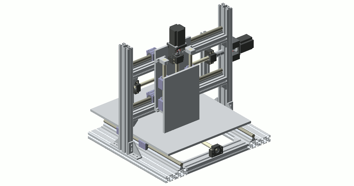
When I just started to develop my first complex OpenSCAD project I didn’t think about the model hierarchy, I just created a lot of parts and added them all into a single assembly file. Soon I realized that this approach was completely wrong as it was nearly impossible to navigate in such an assembly, just imagine this approach with the following design:
Adding a new part and moving it to the desired location turned into a nightmare and I started to think about an easy and maintainable way to solve this problem and now I think I found the right solution.
The idea is inspired by software development. I split each component into two separate files: one containing just dimensions and another one with the implementation itself. In this way I get the most out of OpenSCAD inclusion mechanism. From OpenSCAD wiki:
For including code from external files in OpenSCAD, there are two commands available:
include <filename>acts as if the contents of the included file were written in the including file, anduse <filename>imports modules and functions, but does not execute any commands other than those definitions.
For us it means that we can “include” all files with dimensions and “use” files with the implementation and helper functions. Why not just include everything? Because of two reasons:
- Naming conflict. Inclusion makes all variables in the included file available in the including file, so if you use some simple names like “D” for diameter, “L” for length and so on in both files then you are in trouble. You can rename that variables using “part_name_var_name” pattern in order to resolve naming conflict, but this will make your internal formulas much bigger.
- Debugging code. Just look at the following sample file:
use <bom.scad>
include <colors.scad>
include <profile_30_dim.scad>

module profile_30x30(length)
{
    color(color_alu)
    translate([0,0,profile_h])
    rotate([0,90,0])
    linear_extrude(length)
    import("Profile_30x30_B.dxf");
    bom_item(str("profile_30x30x", length));
}

profile_30x30(100);
As you probably noticed, there is an instance of the model at the end of the file, which is very useful for debugging. If we include that file instead of calling “use” we would create this debug instance as well and this is definitely not something we want.
Inclusion section of your assembly should look like the following at the end:
/* Ball screw */
use     <parts/sfu1605.scad>
include <parts/sfu1605_dim.scad>
/* Ball screw nut */
use     <parts/sfu1605_nut.scad>
include <parts/sfu1605_nut_dim.scad>
/* Ball screw nut housing */
use     <parts/sfu1605_nut_housing.scad>
include <parts/sfu1605_nut_housing.scad>
/* Ball screw fixed end support */
use <parts/bk12.scad>
include <parts/bk12_dim.scad>
/* Ball screw floating end support */
use <parts/bf12.scad>
include <parts/bf12_dim.scad>
I’ve been using this approach for a lot of time and I’d say it’s a proven design, which saves me a lot of time.