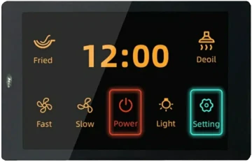
I was looking for a relatively inexpensive module with BLE and capacitive touch and found this gem. It has ESP32-WROVER-B module, 3.5 inch SPI display with capacitive touch, USB type C connector and two expansion board connectiors.

It took me about two evenings to implement what I wanted, but I was a bit disappointed that this board was working only with USB Type A -> Type C cables. When I tried to connect Type C -> Type C cable, there was no power. As usual, the solution was very simple. It could be that you have a newer version, where this issue has already been fixed, but my version (3.2) still has this problem.
Let’s go back into history and check where is the difference between old connectors and a new type C connector.
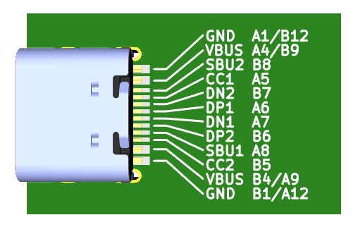
Old connector has just four lines: two for power and two for data transmission. 5 Volts are applied to the power lines regardless of the connection status. Type C connector works in a bit different way. There is no voltage by default, but there are two configuration channels (CC1 and CC2). These wires are pulled up on the host side and should be pulled down on the device side. Recommended pull-down resistance is about 5kOhm.
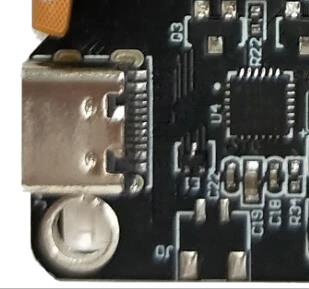
Now let’s take a look at our hero:

There are no resistors! No wonder, that the host does not want to give the power to the board. So, all we need to do is just to solder two resistors between each of CC lines and ground. Easy to say, but hard to solder. Here is the picture, that will help you to identify these lines:

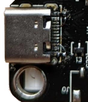
Here is how I soldered these two resistors (I had 4.7kOhm in 0402 package):

Looks a bit dirty, because I didn’t want to wash the board with the display connected to it, but works perfectly.